80/20m CW/SSB Transciever
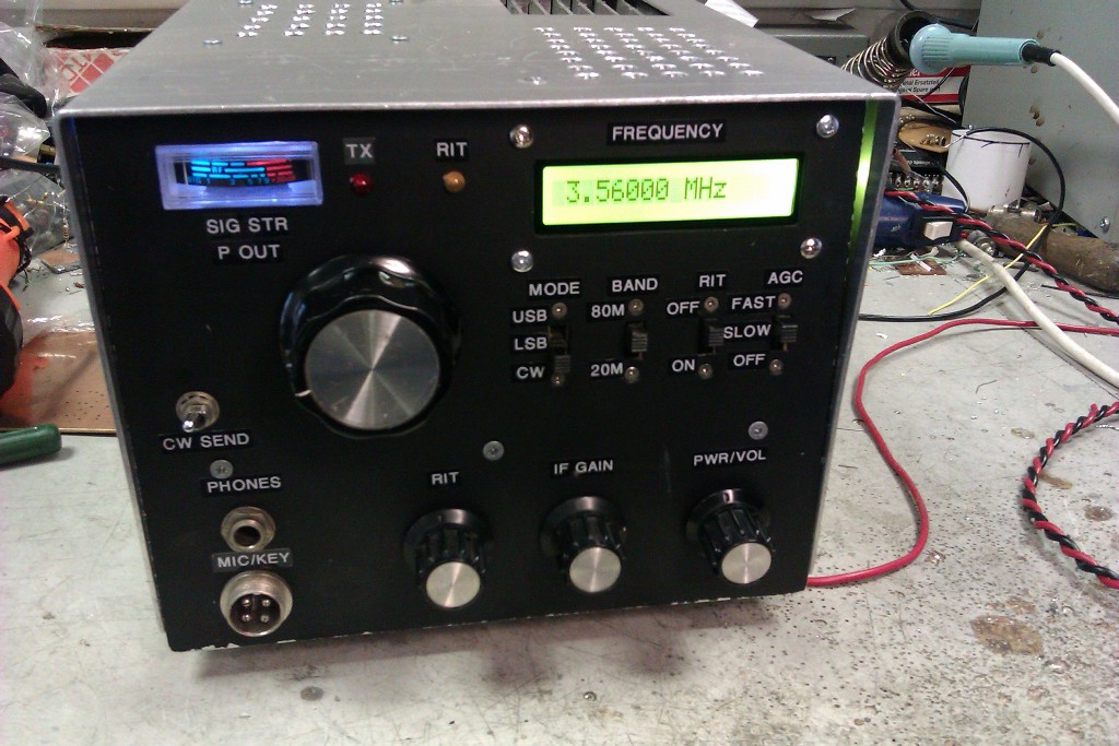
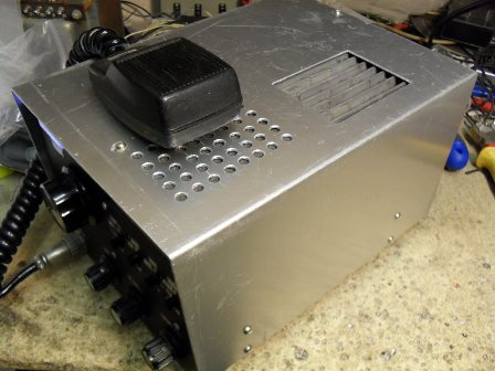 This is a SSB and CW transceiver for the 80m and 20m bands. It produces 25 Watts out and uses a digital frequency display. Once again this set was built to take on camping holidays but I also wanted the option of SSB rather than just CW. All circuit diagrams are given along with a brief description. The set was built modular style so designing/testing is much easier. A single conversion superhet is used for RX with an IF of 9MHz exactly. This allows cheap comercial crystal filters ( G-QRP Club ) to be used and has the benifit of covering both 80m and 20m with the same VFO. Due to the mixing process, there is a side band inversion on 80m and the VFO tunes backwards. The side band inversion is taken care of with logic, VFO tuning is not a problem as a digital readout is used. The VFO tunes from 5Mhz to 5.5MHz thus giving coverage from 3.5 - 4MHz and 14 - 14.5MHz. Stability of the VFO is very good, drift is less than 100Hz in any one hour after an initial warm up period of 15 minutes. All signal routing / switching is done using DC "wetted" relays rather than PIN diodes to preserve intermod performance.
The VFO
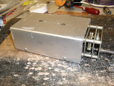
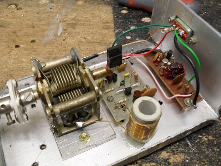 The VFO consists of a series tuned colpits oscillator followed by a buffer stage and then a broad band amplifier to raise the level suitable to driving th LO port of the SBL-1 double balanced diode ring mixer. Sound mechanical construction is key for a good VFO. A ceramic former with no core is used for the tuning inductor in the oscillator along with a good quality tuning capacitor, a reduction drive is also used with the tuning capacitor. Here is the
circuit diagram for the VFO.
The RF PA
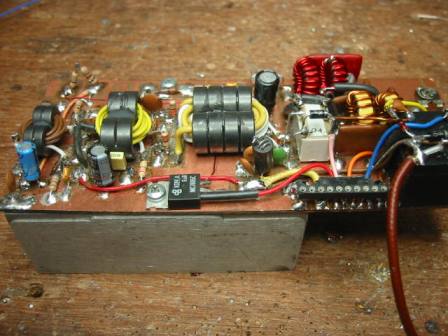
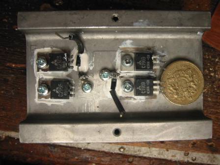 The RF PA consists of a push pull driver pair followed by the push pull final. The RF transformers are made from stacked torroid cores. The PA can produce up to 35 Watts but keep it to 25 Watts for best lineararity. circuit diagram for the RF PA.


Board 1
This board contains the carrier crystal oscillators, the PA pre driver, 80 and 20m bandpass filters and finaly the audio side tone oscillator. There is no particular order to the boards and what they contain, i just made it up as i went along. Circuit diagram in pdf format
Board 2
Contains the IF, Mic pre amp, Audio pa, DSB generator and the CW transmit carrier osc. Circuit diagram in pdf format


Board 3
This board contains the crystal filters , mixer and post mixer amplifier. Circuit diagram in pdf format
board 4
contains all the relays for the various ht supplies/logic. Circuit diagram in pdf format
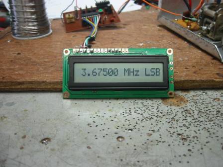
Digital frequency display
I used VK3BHR's excellent PIC frequency counter for a digital readout. I modified the source code to remove the USB and LSB legends.
AGC board
Here is the circuit diagram of the agc board. Audio derived agc is used, however full wave rectification of the audio sample is used thereby doubling the sampling rate which gives a more reactive/smoother agc. You will notice the audio section of the circuit is identical to my audio intercom, by converting the audio to balanced audio then rectifing it is an easy way to acheive full wave rectification of the audio waveform. Think of it as a center tapped transformer with a diode on the two outer legs and center tap to ground.
Here are a few more photos of the set Photo 1
Photo 2
Photo 3
Photo 4
Photo 5
HOME

 This is a SSB and CW transceiver for the 80m and 20m bands. It produces 25 Watts out and uses a digital frequency display. Once again this set was built to take on camping holidays but I also wanted the option of SSB rather than just CW. All circuit diagrams are given along with a brief description. The set was built modular style so designing/testing is much easier. A single conversion superhet is used for RX with an IF of 9MHz exactly. This allows cheap comercial crystal filters ( G-QRP Club ) to be used and has the benifit of covering both 80m and 20m with the same VFO. Due to the mixing process, there is a side band inversion on 80m and the VFO tunes backwards. The side band inversion is taken care of with logic, VFO tuning is not a problem as a digital readout is used. The VFO tunes from 5Mhz to 5.5MHz thus giving coverage from 3.5 - 4MHz and 14 - 14.5MHz. Stability of the VFO is very good, drift is less than 100Hz in any one hour after an initial warm up period of 15 minutes. All signal routing / switching is done using DC "wetted" relays rather than PIN diodes to preserve intermod performance.

 The VFO consists of a series tuned colpits oscillator followed by a buffer stage and then a broad band amplifier to raise the level suitable to driving th LO port of the SBL-1 double balanced diode ring mixer. Sound mechanical construction is key for a good VFO. A ceramic former with no core is used for the tuning inductor in the oscillator along with a good quality tuning capacitor, a reduction drive is also used with the tuning capacitor. Here is the

 The RF PA consists of a push pull driver pair followed by the push pull final. The RF transformers are made from stacked torroid cores. The PA can produce up to 35 Watts but keep it to 25 Watts for best lineararity.


